If we put all of this information together, one TPF system can have PU 5 NCP connections, PU 5 CTC connections, and PU 2.1 ALS connections, all at the same time. This one TPF system can reside in many different networks at the same time. The more interesting question is "In which network does a given TPF application reside?" The answer is, of course, "It depends."
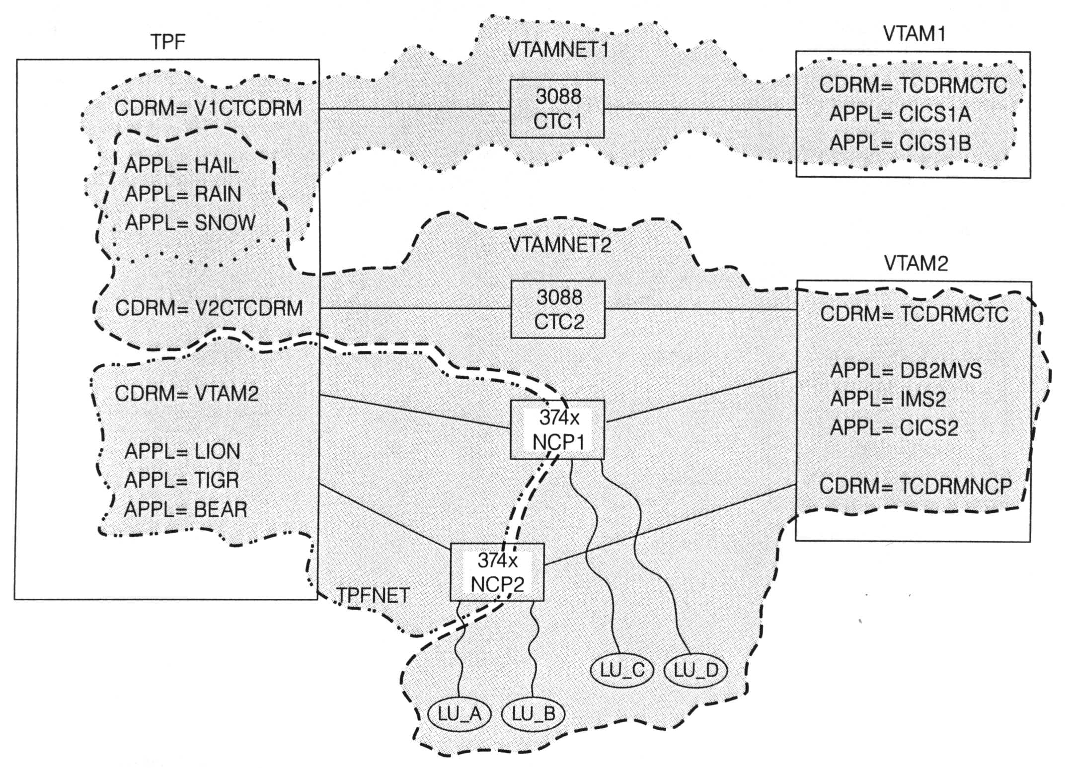
For the first example, the TPF system has only PU 5 connections as shown in Figure 1. In this example:
While the TPF system can reside in different networks at the same time, a given TPF application can reside in only a subset of those networks. In reality, there is one big, happy TPF system in this example, but to the remainder of the network there appears to be three separate TPF systems, as shown in Figure 2:
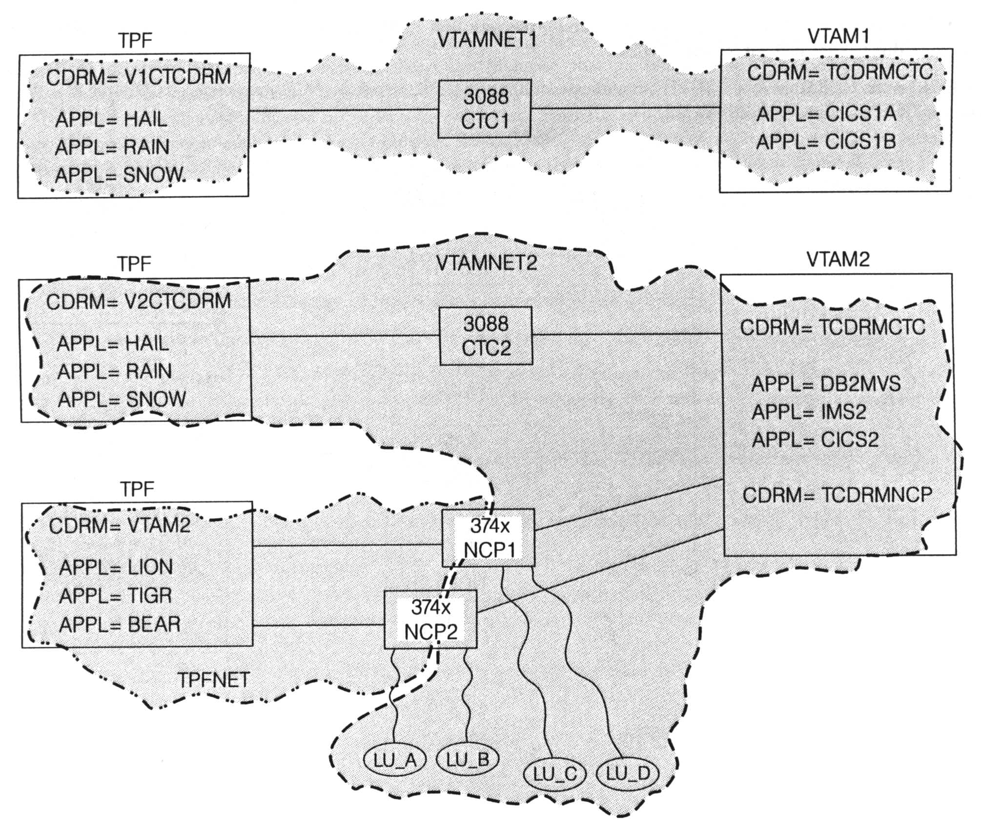
(figure 2)
The communication to each of the three logical TPF systems uses a different CDRM-CDRM session, which allows the one physical TPF system to present different images based on connection type. On host VTAM2, for example, each TPF application is defined, and part of that definition includes which CDRM owns that application. Applications HAIL, RAIN, and SNOW are owned by CDRM TCDRMCTC. Applications LION, TIGR, and BEAR are owned by CDRM TCDRMNCP. This means that the same TPF application accessed by a VTAM application across the CTC connection cannot be accessed by terminals across the NCP connections.If you did want to be able to access the same application from both CTC and NCP connections, you would need to assign that application two different LU names that map to the same program in TPF. Remember that the TPF application name is just the name of the LU that is used to interface to the SNA network. In the example, applications SNOW and TIGR could be defined so that they both represent the same program in TPF (same real application, two different LU names) . . . a box of roses by any other name still contains roses when you unwrap the package. Whether you call it a box of roses or an "I'm sorry I forgot your birthday" makeup gift, it is still just roses.
The next "wrinkle" to throw into our network example is Advanced Peer-to-Peer Networking (APPN). APPN is designed to replace the PU 5 NCP connections. The PU 5 CTC connections remain unchanged by APPN and are still your best choice for sessions between adjacent hosts. Using the previous example, we will look at migrating the PU 5 NCP connections to APPN. We will do this in such a way that a gradual migration can be done rather than the "all-at-once" approach (also known as the "big prayer" approach).
In order for remote LUs connected across APPN connections to access the same TPF applications that are accessed by remote LUs across PU 5 NCP links, the PU 5 and PU 2.1 network identifiers in TPF must be the same. In other words, set the value of the LENNETID parameter in CTK2 to be the same value as the NETID parameter. In our example, TPFNET.LION, TPFNET.TIGR, and TPFNET.BEAR are the network-qualified names of the TPF applications as defined to host VTAM2. The terminals that log on to the TPF applications know only the unqualified name (for example, LION, not TPFNET.LION). One of the goals in migrating to APPN is to not have to change the remote LUs at all. In a large network where there are over 100,000 remote LUs accessing a TPF application, it is not feasible or manageable to try to change some or all of those LUs to log on to a different name.
By setting the LENNETID parameter to the value TPFNET, the name of TPF applications across the APPN connections is the same name as across the PU 5 NCP connections. Assume the control point (CP) name of the TPF system in our example is TPCP. On host VTAM2, application TPFNET.LION would be defined as owned by CDRM TCDRMNCP and also owned by CP TPCP. This enables the TPF application to be defined in both the PU 5 and APPN networks at the same time. Through various VTAM start options and definitions, you can control which network is searched first when trying to start a session with the TPF application. By doing so, you can migrate part of the network at a time from PU 5 to APPN and still have all the terminals access the TPF application. The migration from PU 5 to APPN is transparent to the remote LUs.
Figure 3 shows the network when the connection to device NCP2 has been converted to APPN and is now named ALS2.
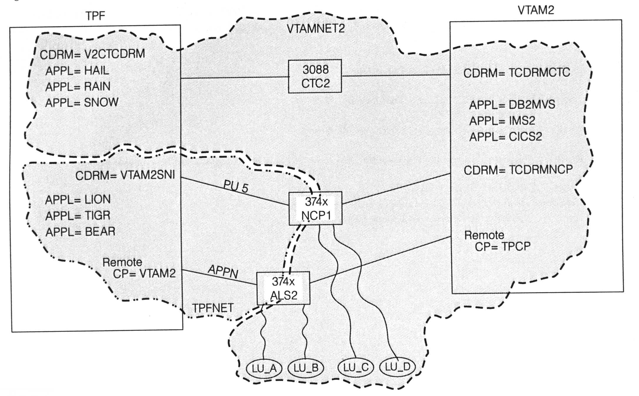
(figure 3)
Terminals LU_C and LU_D would continue to access TPF application LION through the PU 5 network. Terminals LU_A and LU_B would now access TPF application LION through the APPN network. LU_A and LU_B are unaware that any network changes have been made. As far as these terminals are concerned, they just log on to application LION, which is what they have always done.When your TPF system has PU 5 SNI connections and APPN connections to the same VTAM system, CDRM aliasing must be used. In our example, the SSCP name and CP name of the VTAM host is VTAM2. The SSCP name and CP name of a VTAM host must be the same. Resource VTAM2 must be defined as a remote CP (not a CDRM) to your TPF system. To define the CDRM of the VTAM2 host to TPF, an alias name must be used and associated with the real name of the CDRM. The CDRM name defined to TPF in Figure 3 is VTAM2SNI. On the CDRM statement that defines that resource to TPF, REALNAME=VTAM2 must be coded. This parameter defines to TPF the real name of the CDRM. To display, activate, or deactivate the CDRM from the TPF operator console, name VTAM2SNI (the alias CDRM name) must be used. To display, activate, or deactivate the APPN CP-CP sessions, specify name VTAM2 (the real CP name) on the TPF operator command.
To summarize, what is the correct response when you are asked about the location or owner of a TPF application? The answer is that it depends on who is asking.